Voltage drop across capacitor formula
The capacitor takes I C current that leads voltage by 90. So it desires an energy boost for the passage through the external circuit again.

Capacitive Voltage Divider
Hence the voltage drop is 90 V.

. Considering first the DC circuits having only DC voltage sources the inductors and capacitors behave as short circuits and open circuits respectively in steady-state. A capacitance of one farad F means that one coulomb of charge on each conductor causes a voltage of one volt across the device. The knee voltage value for Si diode is 07 volts for Ge diode it will be 03.
By using voltage drop calculation formula we get V I Z. Calculate the value of the voltage from. For finding the voltage across a capacitor the formula is VC QC.
We can calculate the amount of allowable ripple by the formula below. Find the overall capacitance and the individual rms voltage drops across the following sets of two capacitors in series when connected to a 12V AC supply. Use the proper formula or equation according to the condition.
The capacitor supplies leading reactive component and reduce the effect of lagging reactive component. The formula which calculates the capacitor current is I Cdvdt where I is the current flowing across the capacitor. The flow of electric current creates a magnetic field around the conductor.
Our universal formula for capacitor voltage in this circuit looks like this. Area A 050 m 2 Distance d 004 m relative permittivity k 1 ϵ o 8854 10 12 Fm. Calculate the parallel plate capacitor.
Voltage is a measure of the potential difference between two points as it is applied across a wire or an electric component. The field strength depends on the magnitude of the current and follows any changes in current. Therefore the output voltage V Z 50V.
For example for low voltage types a 10 V electrolytic capacitor has a dielectric thickness of only about 0014 µm a 100 V electrolytic capacitor of only about 014 µm. Points on the current. Vkp K IfCTR x RCT RL RR Where.
Find the voltage drop across the circuit. Also called chordal or DC resistance This corresponds to the usual definition of resistance. Since the voltage across zener diode is greater than VZ which is 50 V the zener is in the on state.
Put the values of required quantities like R C time constant voltage of battery and charge Q etc. Here we are taking an example of a 100 ft power line. A parallel plate capacitor kept in the air has an area of 050m 2 and is separated from each other by a distance of 004m.
Supply Voltage Sum of the voltage drop across each component of the circuit. At last between the points F and G the voltage drop is 3V. A common use of the term voltage is in describing the voltage dropped across an electrical device such as a resistor.
Because the thickness of the effective dielectric is proportional to the forming voltage the dielectric thickness can be tailored to the rated voltage of the capacitor. Before connecting capacitor the load current is I L. C The capacitance.
For DC closed circuits we also use Kirchhoffs circuit law for voltage drop calculation. Resistance is the measure of the opposition to the current in a circuit. Voltage drop across the resistance Input voltage Vz 120 50 70 V.
Angle between voltage V and I R is decreased compared to angle between V and I L. With our money back guarantee our customers have the right to request and get a refund at any stage of their order in case something goes wrong. Voltage Formula 2 Power And Current The power transferred is the product of supply voltage and electric current.
What is the current across a capacitor if the voltage is 5cos120t and the capacitance is 02F. Static resistance determines the power dissipation in an electrical component. Ex2 How to find voltage drop by using the voltage drop formula when a current flow is 17A through that carries resistance of 26 Ω.
Load current VzRL 5 mA. So after 725 seconds of applying a voltage through the closed switch our capacitor voltage will have increased by. It consists of two parallel plates separated by a dielectric.
Mathematically power factor is the product of voltage drop across the element and current flowing through it. The parallel plate capacitor formula is expressed by. So for 2 lines 2 100 ft.
Because the conductors or plates are close together the opposite charges on the conductors attract one another due to their electric fields allowing the capacitor to store more charge for a given voltage than when the conductors are separated. Thus by using the equation we get voltage drop across the circuit 60 Volts. The voltage drop is the difference between the.
Voltage Drop Calculation of a DC Power Line. For the peak voltage across the transformer primary to be 17V12sqrt2 and the total drop across the diodes to be 207V 14V the peak voltage across the capacitor is about 15V approx. Impedance Z 20 Ω.
The knee point voltage of ct can be calculated using the following formula. When we connect a DC voltage source across the capacitor one plate is connected to the positive end plate I and the other plate to the negative end plate II. The capacitor has certain endurance power to handle a maximum voltage.
The portion of the circuit between the points G and H there is no energy for the charge. The voltage drop across the device can be understood as the difference between measurements at each terminal of the device with respect to a common reference point or ground. The voltage divided by the current R s t a t i c U I.
The conventional volt V 90 defined in 1987 by the 18th General Conference on Weights and Measures and in use from 1990 is implemented using the Josephson effect for exact frequency-to-voltage conversion combined with the caesium frequency standardFor the Josephson constant K J 2eh where e is the elementary charge and h is the Planck constant a. V 12 20. V 240 V.
Electronics Hub - Tech Reviews Guides How-to Latest Trends. There is a notation on the capacitors and the maximum voltage for a capacitor lies between 15V to 100V. At this point the voltage 3V becomes 0V.
When the potential of the battery is applied across the capacitor plate I become positive with respect to plate II. First identify the situation whether the capacitor is charging or discharging or at saturation condition. Displaystyle R_mathrm static frac UI It is the slope of the line chord from the origin through the point on the curve.
Since we started at a capacitor voltage of 0 volts this increase of 14989 volts means that we have 14989 volts after 725 seconds. This is provided by the power source as the charge passes from H to A. This barrier voltage at which the flow of current will increase is known as knee voltage.
Inductance is the tendency of an electrical conductor to oppose a change in the electric current flowing through it. And the resultant current of the system is I r. Here Q amount of charge stored on each plate.
Now put in the above equation we get 1 Thus we get voltage equals the power divided by current. Given Current 12A. Hence the entire circuit behaves as a resistive circuit and the entire electrical power is.
Therefore it can be represented by a battery of 50 V. C X is the capacitance of the capacitor in question V S is the supply voltage across the series chain and V CX is the voltage drop across the target capacitor. It is as follows.
Capacitors In Series And Series Capacitor Circuits

Finding The Voltage Drop Across Capacitors Electrical Engineering Stack Exchange

Kirchhoff S Voltage Law Kirchhoff S Current Law Kirchhoff S Law Kcl Kvl How To Be Outgoing Physics Formulas Law

Capacitors In Series And Series Capacitor Circuits
What Will Be The Voltage Of A Capacitor After 2 Seconds Of Closing The Switch If It Is Initially Charged To 2 Volts Quora

Arduino 3 Phase Inverter Circuit With Code Homemade Circuit Projects Arduino Circuit Projects Circuit
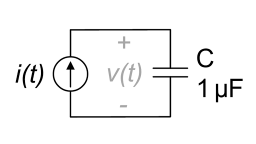
Capacitor I V Equation In Action Article Khan Academy

Capacitors In Series And Series Capacitor Circuits
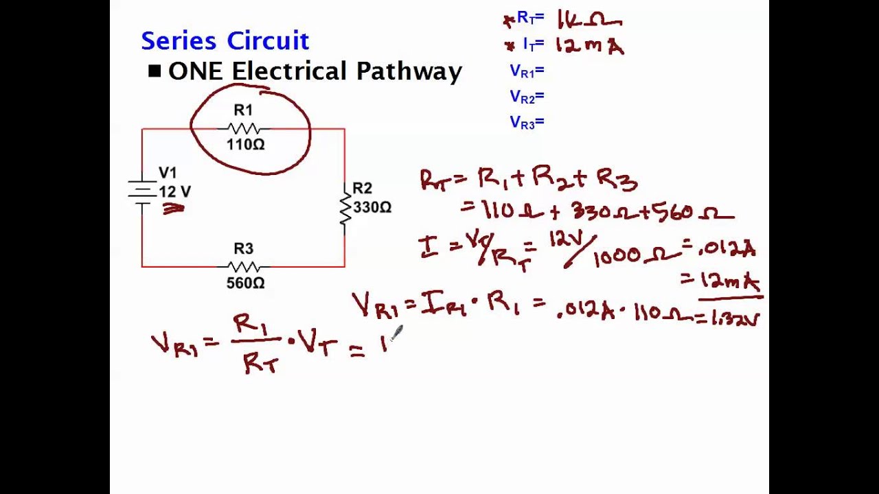
Calculating Voltage Drop Across Resistors Youtube

Capacitors In Series And Series Capacitor Circuits

Pin On Electronic Circuit Diagrams

Capacitors In Series And Series Capacitor Circuits

How To Understand Electricity Volts Amps Watts And Electrical Appliances Simple Circuit Electricity Electrical Projects

Capacitors 5 Of 11 In Combination Parallel And Series Capacitors Youtube

Capacitors 6 Of 11 In Series Calculating Voltage Drop Youtube

Rc Step Response Article Khan Academy

Dual 5v Power Supply Simulation Power Supply Circuit Electronics Circuit Circuit